|
SILO 6.3 (DRAFT)Year 6, Term 3: NanotechnologyScope and sequence: Calibration, Exponents, Ratios, ScalesFocus: Ratios |
|
Learning
intention: Students
convert between metric units of length, mass and capacity
and make relevant connections to the properties of water.
|
|
|
Overview: Nanotechnology
involves the manipulation of matter on a near-atomic scale which
might suggest that this is beyond what Year 6 students can
investigate, but certain principles such as the ratio between
surface area and volume are manageable and relevant for this age
group. These concepts are scaffolded by looking at the metric
system, calibration and various scales used in science, namely;
ordinal, linear and logarithmic.
|
|
|
NSW Syllabus
|
Australian Curriculum
|
|
"A student selects and uses the
appropriate unit to estimate, measure and calculate volumes and
capacities" (MA3-3DS-02).
|
"Students learn to convert between
common metric units of length, mass and capacity; choose and use
decimal representations of metric measurements relevant to the
context of a problem" (AC9M6M01).
|

Introduction to nanotechnology
A nanometre is one billionth of a metre (i.e., one millionth of a millimetre). The following diagram helps illustrate just how small a nanometre is.
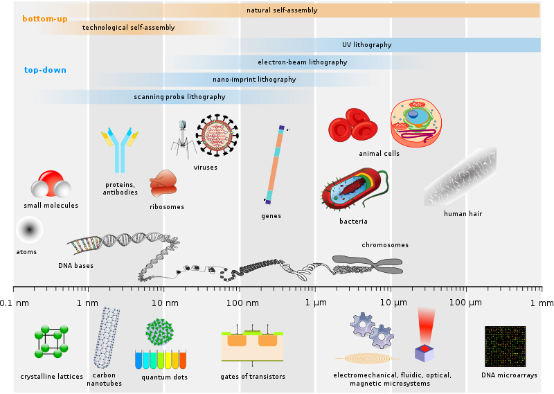
(Image source https://commons.wikimedia.org/wiki/File:Biological_and_technological_scales_compared-en.svg CC BY-SA 2.5)
This video (3:29) explains some of the ways in which
nanotechnology is at the cutting edge of science and technology.
The following video (8:43) titled Why A4 Paper is a Mathematical Miracle has been embedded to stop at the 6:02 mark. (If you would like to continue beyond this point, drag the red playhead to the right.)
The following video (12:30) titled You Are The Center of The Universe (Literally) has been embedded to stop at the 3:24 mark. (If you would like to continue beyond this point, drag the red playhead to the right.)
The logic behind the metric system
Exploring the ratio of surface area to volume is one of the key ideas in nanotechnology, but an overview of the logic behind the metric system is also important to understand. The metric system is logical because it is uses the same base 10 system which we use with our number. In addition to this, there are some important things to know about the properties of water and how these how been used to calibrate the Celsius scale for temperature. Water freezes at 0 degrees Celsius and boils at 100 degrees.

- The temperature inside a refrigerator is generally set around 4 degrees Celsius.
- Human bodies are generally around 37 degrees Celsius.
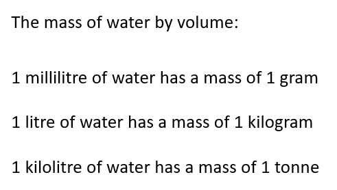
The metric system also uses water as the basis for quantifying volume and mass. This is not coincidental but by design.
Pi (π)
Pi (π) is a number that is the ratio of a circle's circumference (the distance around it) to its diameter (the distance across it). No matter the size of the circle, this ratio is always the same, approximately equal to (3.14). You can think of it as how many diameters it takes to go all the way around a circle—it's always just a little over three times.
 |
|
Volume and capacity
Volume is the total amount of space an object occupies while capacity is the maximum amount of fluid a hollow container can hold.
 |
Mr Wide and Mr TallUsing a piece of paper, make a cylinder shape in either landscape (i.e., Mr Wide) or portrait (i.e., Mr Tall) orientation.Materials required: Paper, tape, blocks. |
We will test which of the two cylinder designs has the greatest capacity using the following steps:
- Each student makes a tall or wide cylinder using a single piece of paper.
- Students do not need to make a bottom for their cylinders as the table will function as the bottom.
- Tops are not required for the cylinders as easy access is required to fill the cylinders with blocks.
- Although overlapping the paper will give the cylinders more rigidity and strength, do not overlap the paper as this will reduce the capacity.
- Use tape to join the two edges of the paper to complete the cylinder.
Teaching tip: There are many ways to test the two designs but the following steps have proven to be effective:
- Find two students with contrasting designs who are willing to be representatives for the other students.
- Ask all of the students with the Mr Tall design to line up behind the Mr Tall representative (and vice versa) ensuring that all students can see the demonstration table.
- Using small construction blocks, fill the Mr Wide cylinder.
- Rather than count these blocks, simply use the same blocks to fill the Mr Tall cylinder after posing the question, "Let's find out if Mr Tall holds the same, less or more?"
Teaching points:
- During the 'Rope activity' in SILO 2.1 'Shapes and objects', we learned that shape is a determining factor when dealing with perimeter and surface area. Today we have seen that shape affects the volume too.
- Mr Wide had the greatest volume because there was an exponent involved.
- Although Mr Tall had the greatest height, height produces a linear increase.
- Mr Wide had the greatest radius and greatest capacity, as radius produces an exponential increase.
- The following formula shows how to calculate the volume of a cylinder.
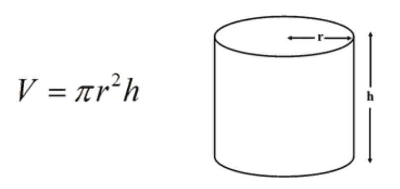
There is a handy online calculator for cylinders at https://www.omnicalculator.com/math/cylinder-volume.
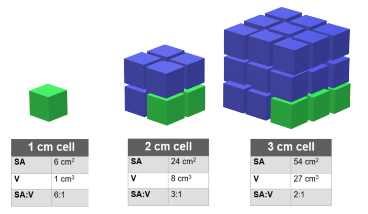
Exploring the ratio of surface area to volume
The main thing to note here is that the ratio of
surface area to capacity is not fixed as shown in the figure below.
There are many examples of this principle in nature. For example:
- Chewing food into smaller pieces aids digestion as the surface area is increased while the volume remains the same.
- Your fingers are the first parts of your body to get cold as they have a high ratio of surface area to volume.
- Elephants have large ears to help them keep cool as their ears also have a high ratio of surface area to volume.
The ratio of surface area to volume can also be seen when building a campfire. It is common to start with kindling because kindling is small which gives it a larger surface area compared to its volume. This is why kindling burns easily.
Exploring solid objects
The following graph shows the surface area (A) against volume (V) of the five Platonic solids and a sphere. Note the following:
- The surface area decreases for rounder shapes.
- The surface-area-to-volume ratio decreases with increasing volume.
- The intercepts with the dashed lines show that when the volume increases 8 (2³) times, the surface area increases 4 (2²) times.

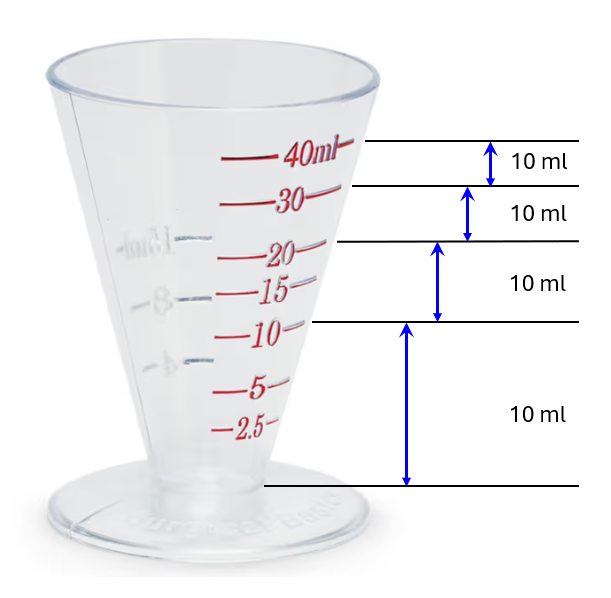
The following image shows some annotations beside a
common medicine cup. Notice how each 10 ml has a different height
due to the conical shape of the cup.
Nanotechnology and medicine
The following video (2:26) contains two examples of how nanotechnology is being used in the field of medical research to fight cancer.
Types of scales
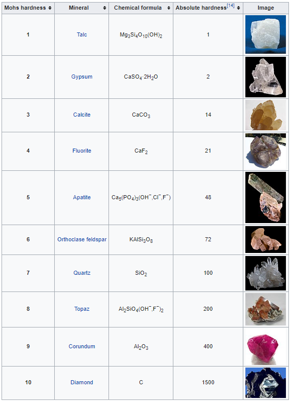
Ordinal scales
An ordinal scale has a non specified degree of variation. In other words, the scale is somewhat arbitrary. An example is the Mohs scale of mineral hardness introduced in 1822 by the German geologist and mineralogist Friedrich Mohs.
 |
What do you notice when you compare the 'Mohs hardness' numbers with the 'Absolute hardness' numbers?Is there a direct correlation?
|
|
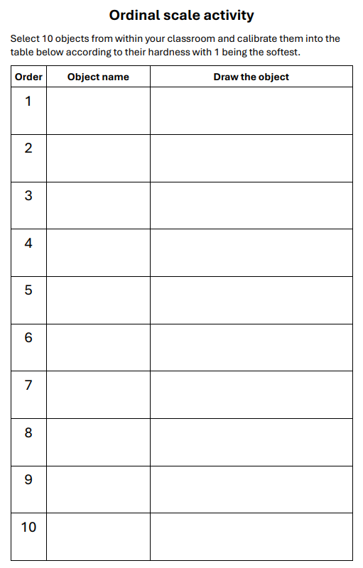
Create your own ordinal scale for hardness using materials in the classroom |
The image below is a table to complete this activity. An A4 worksheet for this activity is available here.
Linear scales
A linear scale has a specified degree of variation. In
other words, there is a direct mathematical correlation along the
scale due to the way that it has been calibrated. An example is the
Celsius scale.
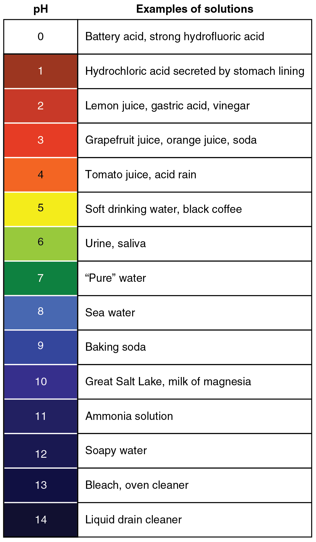
Logarithmic scales
In a logarithmic scale, each interval is increased by a factor of the base of the logarithm, which is often a multiple of 10. Examples of common logarithmic scales are pH (to measure acidity), decibels (sound intensity), and the Richter scale (earthquakes).
|
Review the information provided in the article at https://www.abc.net.au/news/2015-11-19/tropical-cyclone-categories-explained/6956092. Are cyclone categories ordinal, linear or logarithmic?
|
Calibration
Calibration is the process of configuring an
instrument to improve the accuracy of measurements and readings.
The following video (1:39) uses calibration to improve the
accuracy of a digital compass.
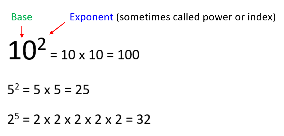
Exponents
Exponents are not part of the curriculum in primary school but they can be discussed and informally introduced in various ways. In the following image you can see that exponents are written in a smaller font. The exponent tells you how many times the base needs to be multiplied by itself.
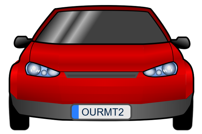
Combinations and permutations
In mathematics, when the order doesn't matter it is a combination. When the order does matter it is a permutation. A permutation is an ordered combination.This means that what are commonly called combination locks are really permutation locks.
|
How many permutations are there with a six-character number plate?Hint: It has something to do with exponents. |
(Answer is at the bottom of this page)
5-bit code
A 5-bit bode has 32 different possibility because 2 to the power of 5 is 32. In the following code, 4 letters have been assigned numbers which have similar shapes to make all 36 characters. Black is 0 and ‘Off’, and white is 1 and ‘On’.
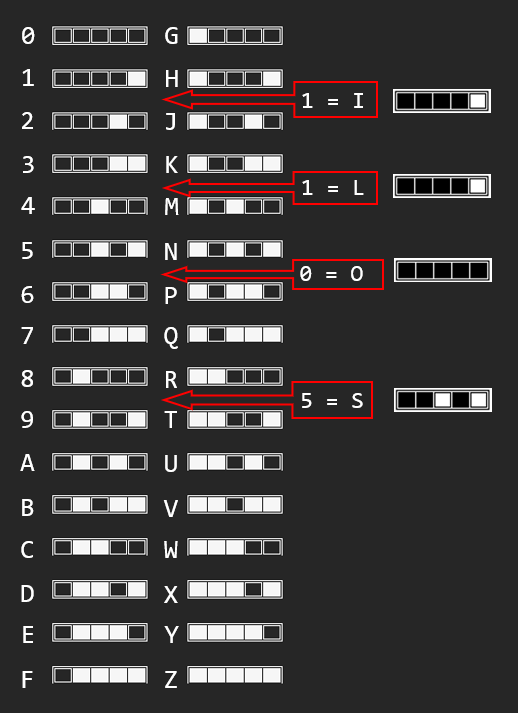
- Do you notice any patterns? Try looking vertically up and down each column starting from the right-hand side.
- Placing your fingers up or down on a desk, count from 0 to 9.
- The Alphabet Song was first copyrighted in 1835 using a French melody from 1761. Sing and code the Alphabet Song three times using (1) preferred hand, (2) other hand, (3) both hands.
Proportionality
The inverse square law
The inverse square law describes how the intensity of a physical quantity radiating from a point source decreases with distance. The intensity is inversely proportional to the square of the distance from the source. This principle applies to various physical phenomena including light, sound, gravity and radiation. The following image shows how the intensity at double the distance is 1/4 of its original value and 1/9 when the distance is three times further.

The International system of units
The International System of Units (abbreviated as SI) is based on the metric system and is the world's most widely used system of measurement. It is the only system of measurement with official status in nearly every country in the world. The seven SI base units are:
| Symbol | Name | Quantity |
| s |
second | time |
| m |
metre | length |
| kg |
kilogram | mass |
| A |
ampere | electric current |
| K |
kelvin | thermodynamic temperature |
| mol |
mole | amount of substance |
| cd |
candela | luminous intensity |
The following image is way beyond what primary school students are expected to know but it is a really good visualisation of how the SI units are related to one another.It is an arrangement of the principal measurements in physics based on the mathematical manipulation of length, time and mass.
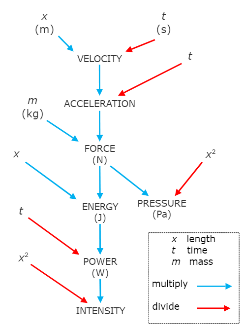
(Image source https://en.wikipedia.org/wiki/International_System_of_Units#/media/File:Physics_measurements_SI_units.png)
Moderated self-assessment
Discussions with students around the key components of conceptual topics and how they fit together can generate insights into student achievement.

------------------
Answer to the exponents question about permutations with six character number plates:
------------------
We welcome your feedback and suggestions
The chief investigator for The SILO Project is Associate Professor Brendan Jacobs, Head of Department STEM Education, University of New England. The SILO Project thrives on incremental improvement so constructive feedback is greatly appreciated. Please contact Brendan via email at bjacobs7@une.edu.au to share your thoughts and recommendations.

This work is licensed under a Creative Commons Attribution-NonCommercial-ShareAlike 4.0 International License
Main menu